This page describes a powerful MW receiver based on two non-EE components (SA612A mixer+oscillator and MK484 radio ic used as a IF amplifier+detector):
There are a two variants of this design:
- A variant with two red IF coils. This design can be built using a single EE2005/1005 kit , and the SA612A (or SA602A / NE612A / NE602A identical variants) as well as the ZN414 or MK484 AM radio chip
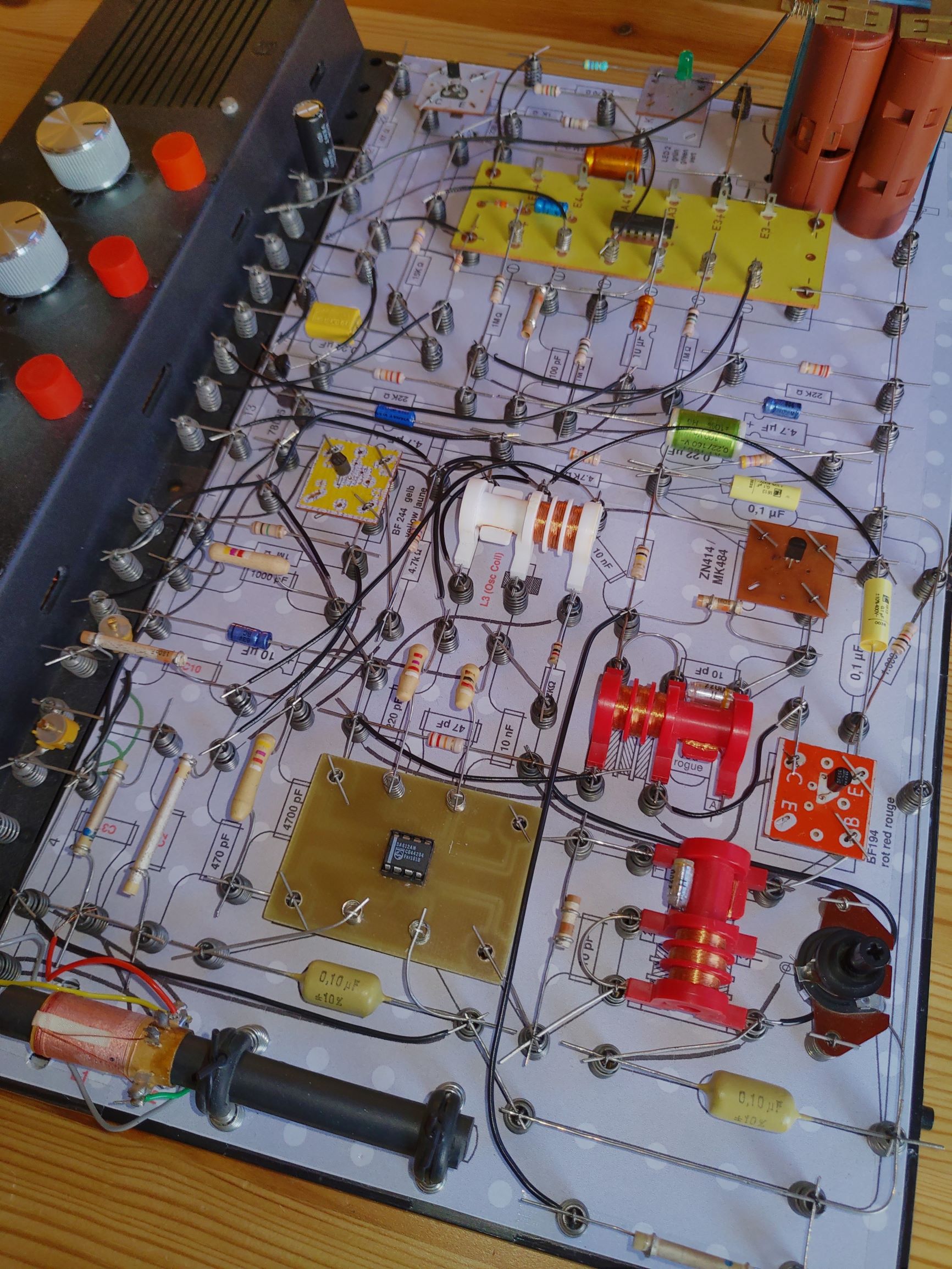
- A variant with three red IF coils (shown in the picture above). This version requires an additional EE2005/1005 kit for the extra IF coil (see Ebay, marktplaats.nl etc.)
Electrical circuit (describing both design variants) and hints for oscillator matching
The electrical circuit diagram contains the extra IF stage indicated in blue:
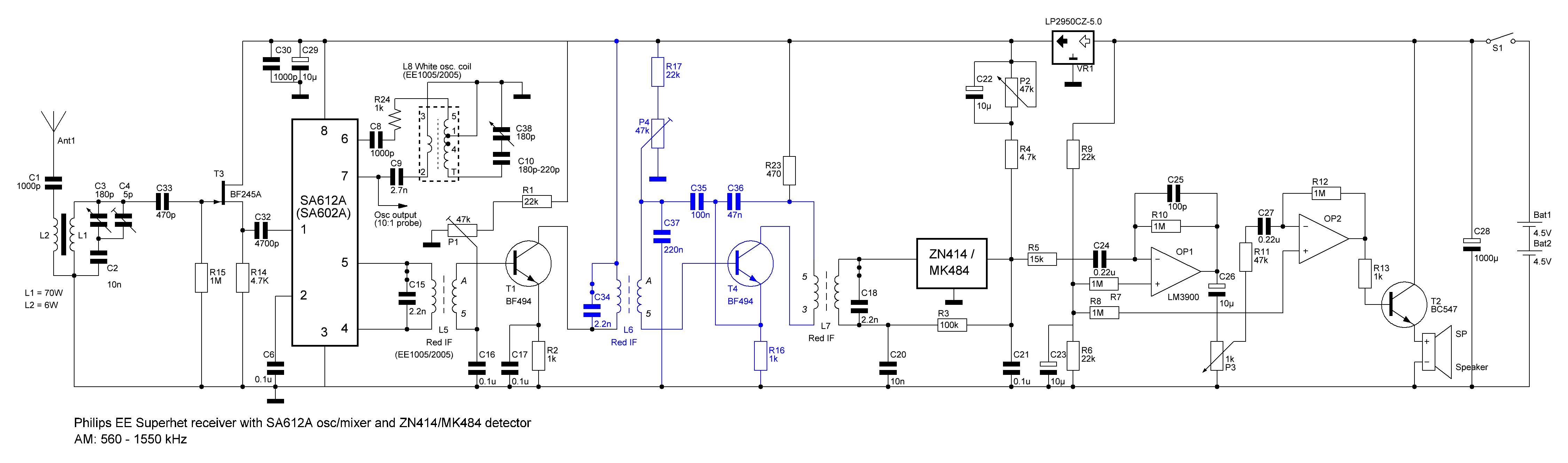
In the circuit above and the layout diagrams below, oscillator series capacitor C10 has not yet been specified. This capacitor is used to match the oscillator range with the ferrite coil antenna range (which is strongly dependent on its position on the ferrite rod). Furthermore its depends on the actual IF frequency applied. According to my experience, the following values will help in finding a good starting position for tuning:
- Coil in position as shown in the pictures on this page
- Oscillator Series Capacitor:
- IF = 515 kHz (my receiver): C10 = 180 pF
- IF = 465 kHz (default): C10 = 220 pF
- Padding trimmers:
- Oscillator padding trimmer: tune (with the help of a frequency meter / oscilloscope) to set the receiving range of the receiver (i.e. F_Osc - F_IF) to a range equal to 560kHz - 1550kHz. The latter seems a good estimate of the ferrite coil antenna receiving range in the indicated position in the pictures
- Ferrite antenna trimmer: tune to balance high-frequency and mid-frequency reception strength for optimal reception over the whole receiving range. Note: the setting of this value is very sensitive and important for proper reception. In my case, the optimal position is at almost minimal capacity.
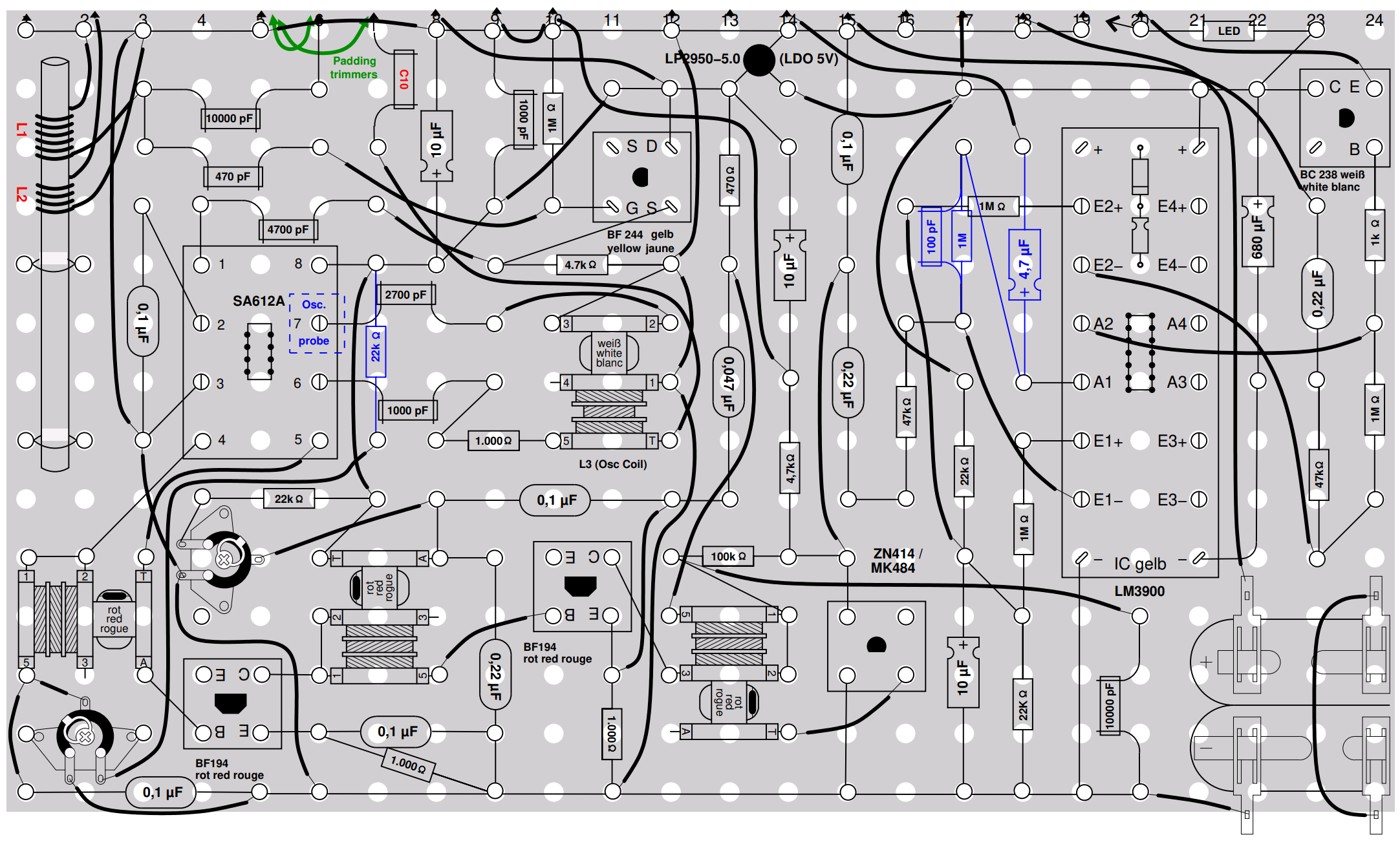
Layout Design file (XFig, WinFig):
The layout files are defined in XFig-format (.fig) as known for UNIX-LINUX based systems, I personally use WinFig on Windows as a good alternative to edit these files
- Two IF-stages (includes indications on extending to three IF-stages with an external board):
- Three IF stages:
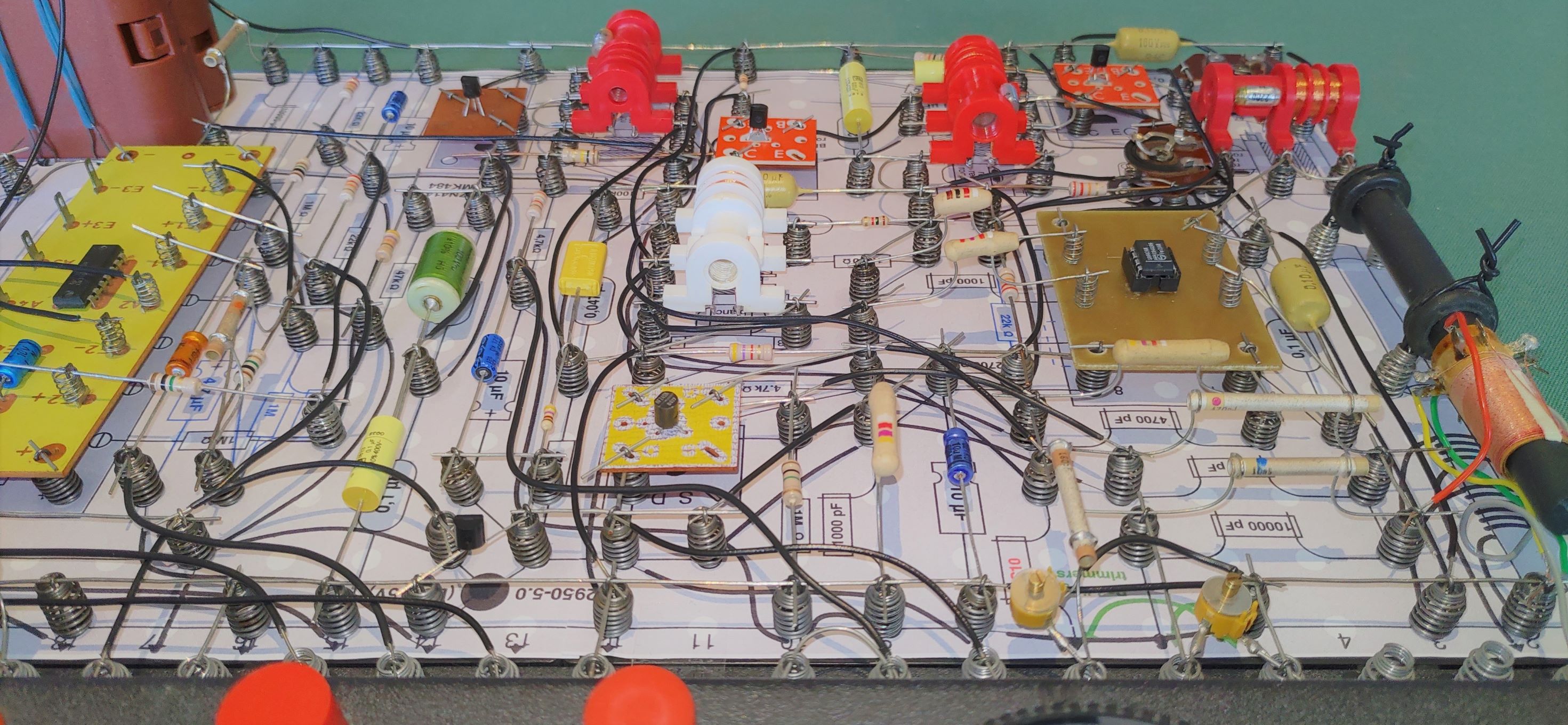
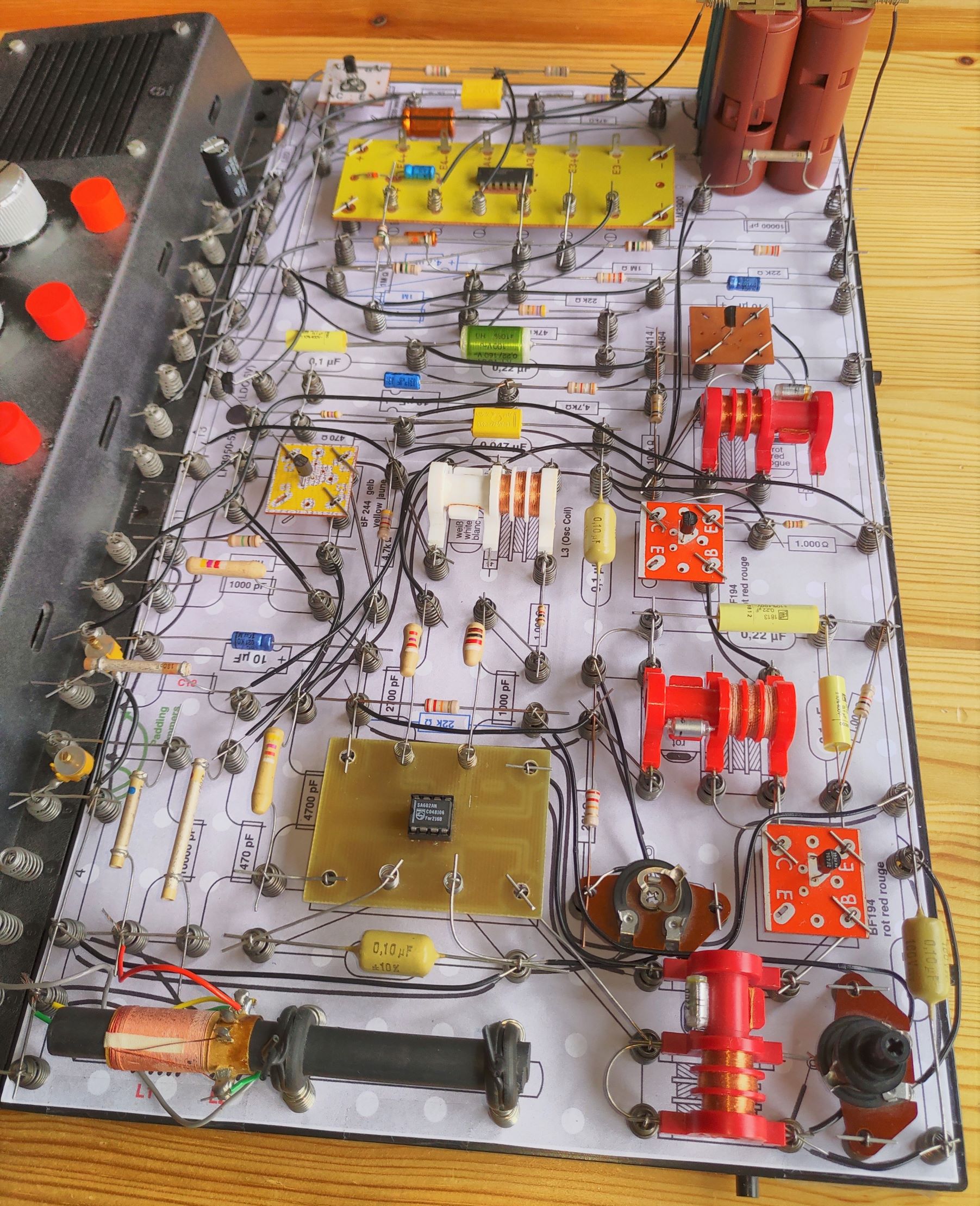
This picture shows the two stage layout in practice:
The picture below shows how the 2-stage design can be extended to the 3-stage version with an external board:
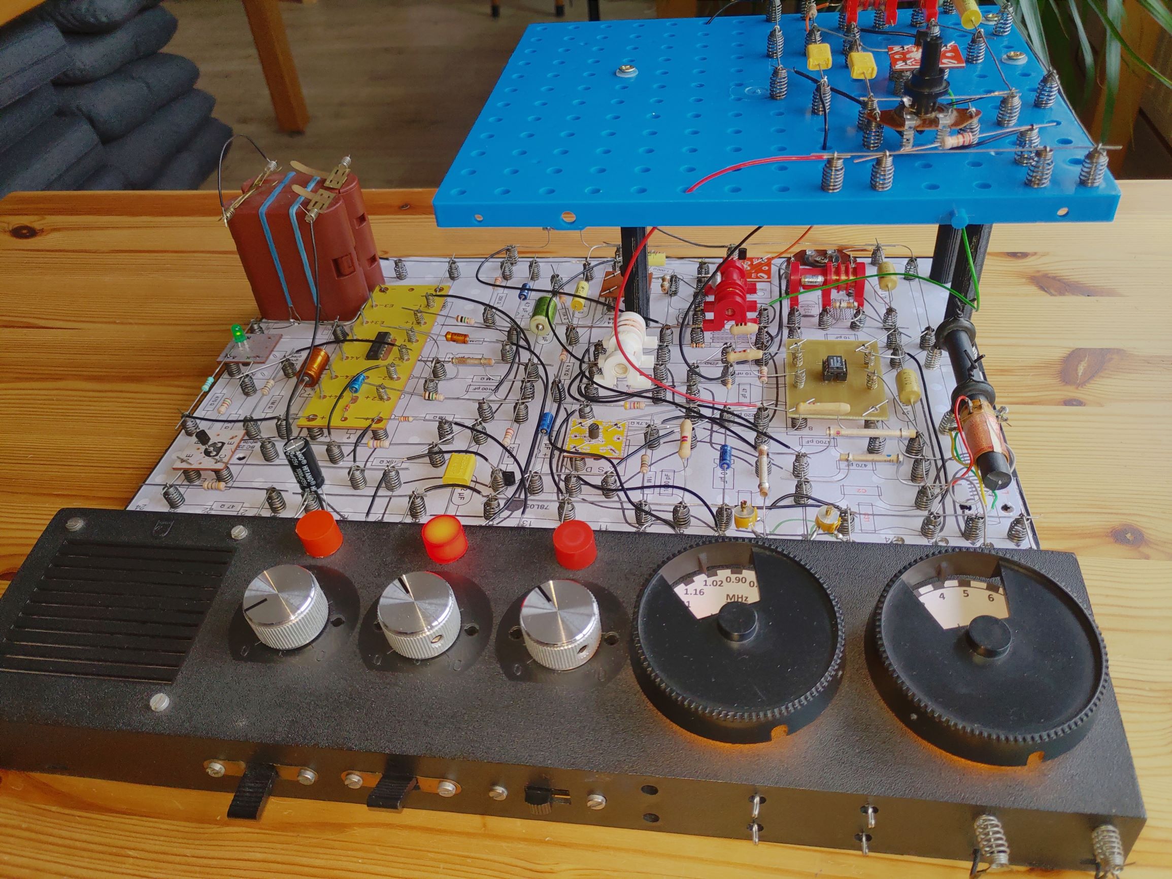
The 3-stage design on a single board then looks like this:
Links concerning this topic:
The development of this receiver has greatly benefitted from the discussions at the following forums, with direct links to these discussions:
- Rigert.com: Alternative Superhet (SA612A mixer & ZN414 detector)
- Circuits Online (NL): Philips EE Nostalgie