The three-transistor MW receiver (nr. 5.02) has likely been one of the most popular designs in the Philips EE series. This radio was depicted on the boxes of the EE2000 series of kits, it was a very successful design that always worked well and did not need an external antenna. It is a so-called "reflex" design, which means that the first amplifier stage is used for both HF and AF signal amplification, as the rectified signal is fed back to the same amplifier.
Although it is a simple, proven design, I wondered in which ways this beautiful receiver could be improved whilst not comprising its reflex concept. It turned out that there were several opportunities that were discussed with and contributed by the active Philips EE community at rigert.com :
- On component level, here are the "low-hanging fruits" that already improve reception:
- Adding a second rectifier diode (replacing the 10 kOhm resistor) for a stronger overall reception (as the two diodes now work as a voltage doubler).
- Reducing the capacitor in the rectifier circuit for 0.1uF to 22 nf for improved and stronger audio (due to a better RC rectification time constant).
- On board design level:
- Re-arranging the audio section such that the volume control is in between the two audio stages instead of before them, to avoid mechanical noise from the audio potentiometer to be strongly amplified.
- On electrical circuit design level, investigating the following two alternatives (both of which are described in the subsections below):
- Adding regeneration (but that implies an additional control for tuning).
- High-impedance RF-input buffering for improved signal reception, for example using a FET-buffer or a emitter-follower circuit.
Alternative 1: The regenerative reflex design
As a first step, it appears that a regenerative extension is very simple and rewarding, improving the sensitivity of the receiver greatly with a minimal effort:
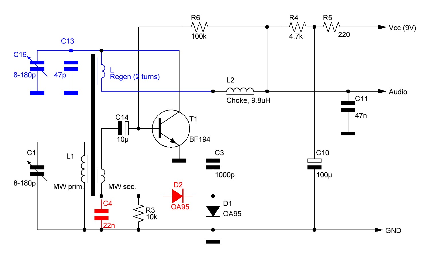
The diagram above shows the component changes in red and the newly added regeneration circuit in blue.
The regeneration concept applied provides a weak coupling that is as independent as possible from the reception frequency. For this reason, the capacitive regeneration control is not in series nor in parallel with the regeneration coil (which would increase the frequency dependency since the coil picks up stronger at higher frequencies anyway) but is used instead to dampen stronger at increasing frequency (see the circuit diagram below) to counter the coil's coupling behavior. Since these capacitors are very small in value they do not affect the audio quality (the regeneration coil carries the audio signal as well, a consequence of the reflex design):
It should be noted that I kept the board layout close to the original 5.02 design for nostalgic reasons, the bending of components can be avoided simply by adding some extra springs. Alternatively one might consider the optimized layout provided here by "Sven" (note that it uses a slightly different regeneration concept).
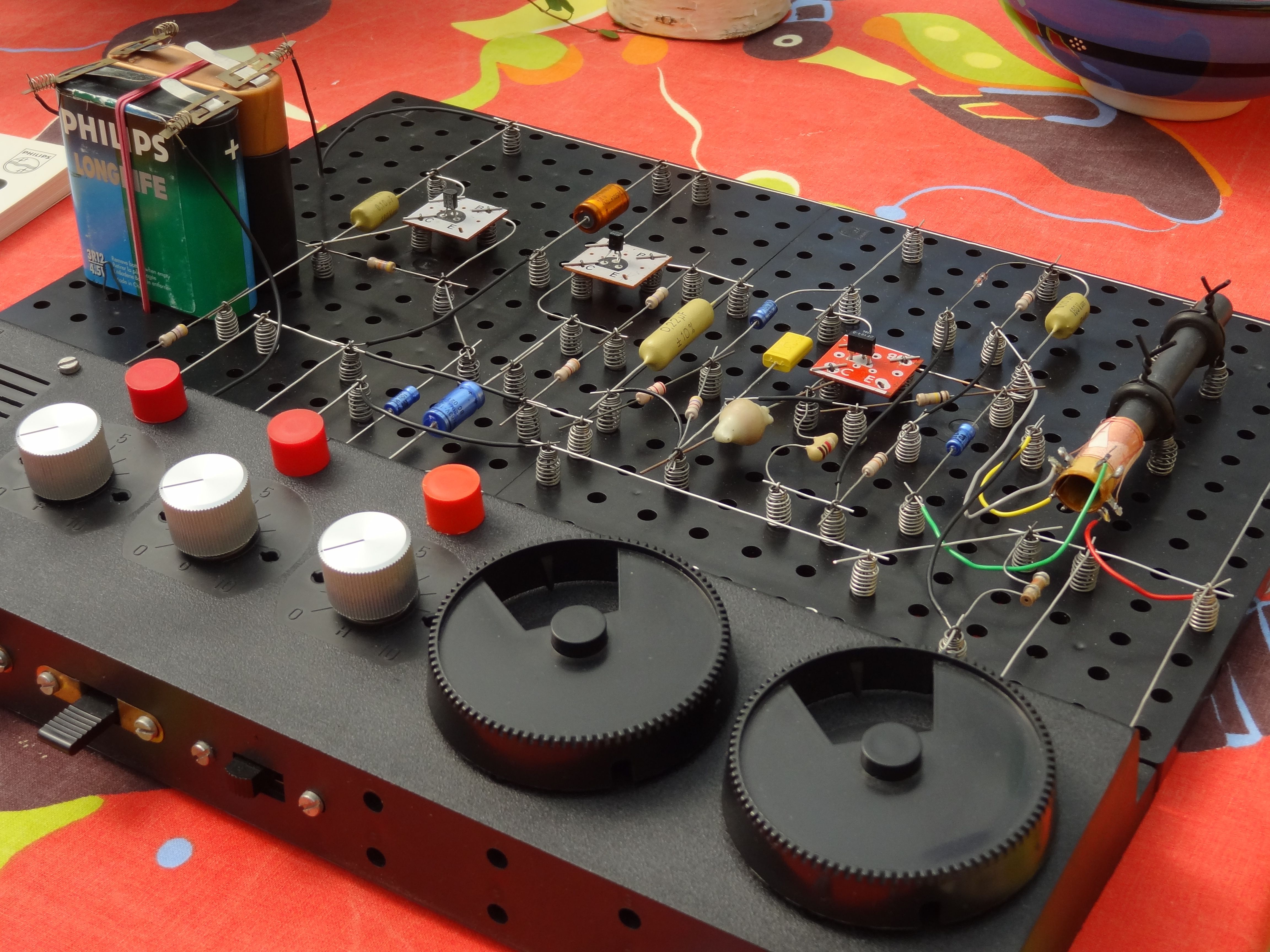
- Picture of the design (showing the coil arrangement with the extra regeneration coil. Note that one ceramic capacitor (1000pf) has disappeared in the final design).
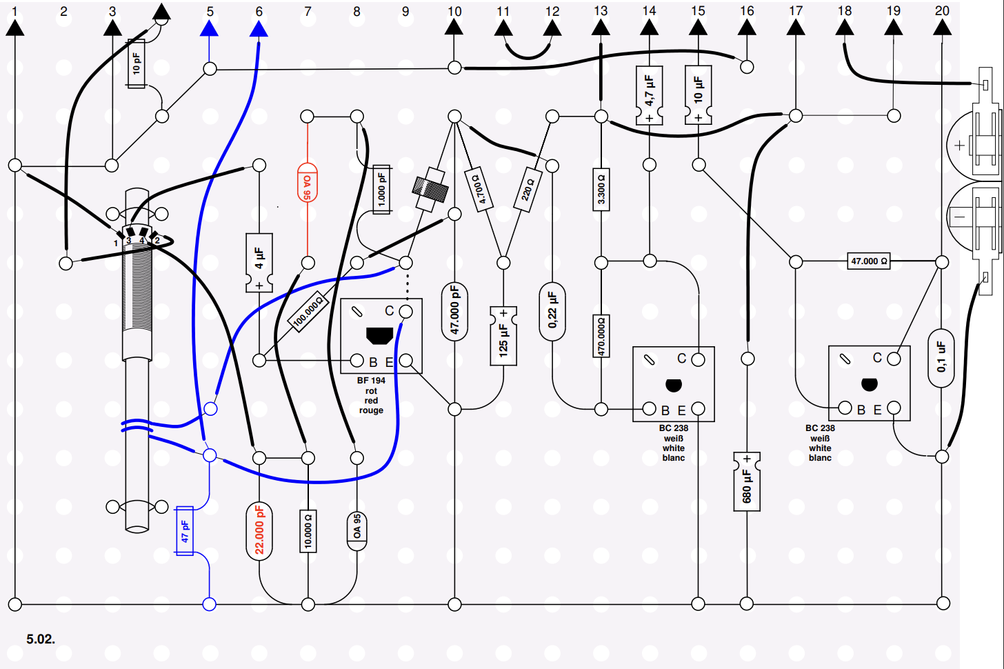
- Electrical circuit design (SPlan) focusing at the regeneration part.
- Electrical circuit design (picture)
- Layout design files:
- Philips EE Layout design (XFig/WinFig)
- Philips EE Layout design (PDF)
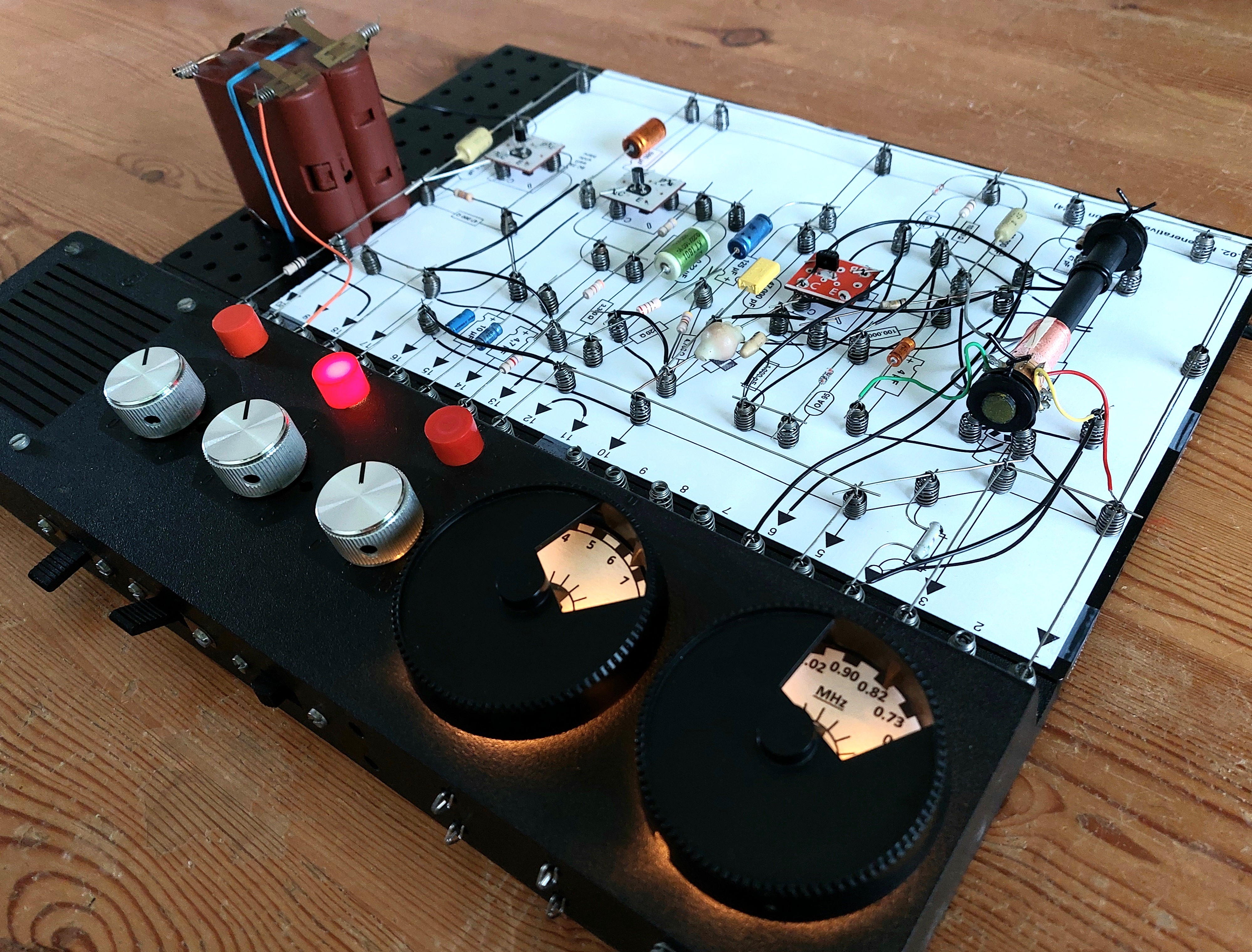
With all the bells and whistles included, this is a very nice receiver (optically and functionally) to use:
Alternative 2: Adding a high-impedance buffer to the original 5.02 design
Although a regenerative design strongly increases both the sensitivity and selectivity of the design, tuning becomes a two-handed affair as well. If one wants to avoid this, a different approach is then to instead add a buffer stage (in this case a FET stage) to the original 5.02 design in between the MW antenna coil and the HF amplifier. Such a design greatly improves both selectivity and sensitivity as well, this time through the very high impedance of the buffer, as it avoids any significant loading of the receiving resonant circuit:
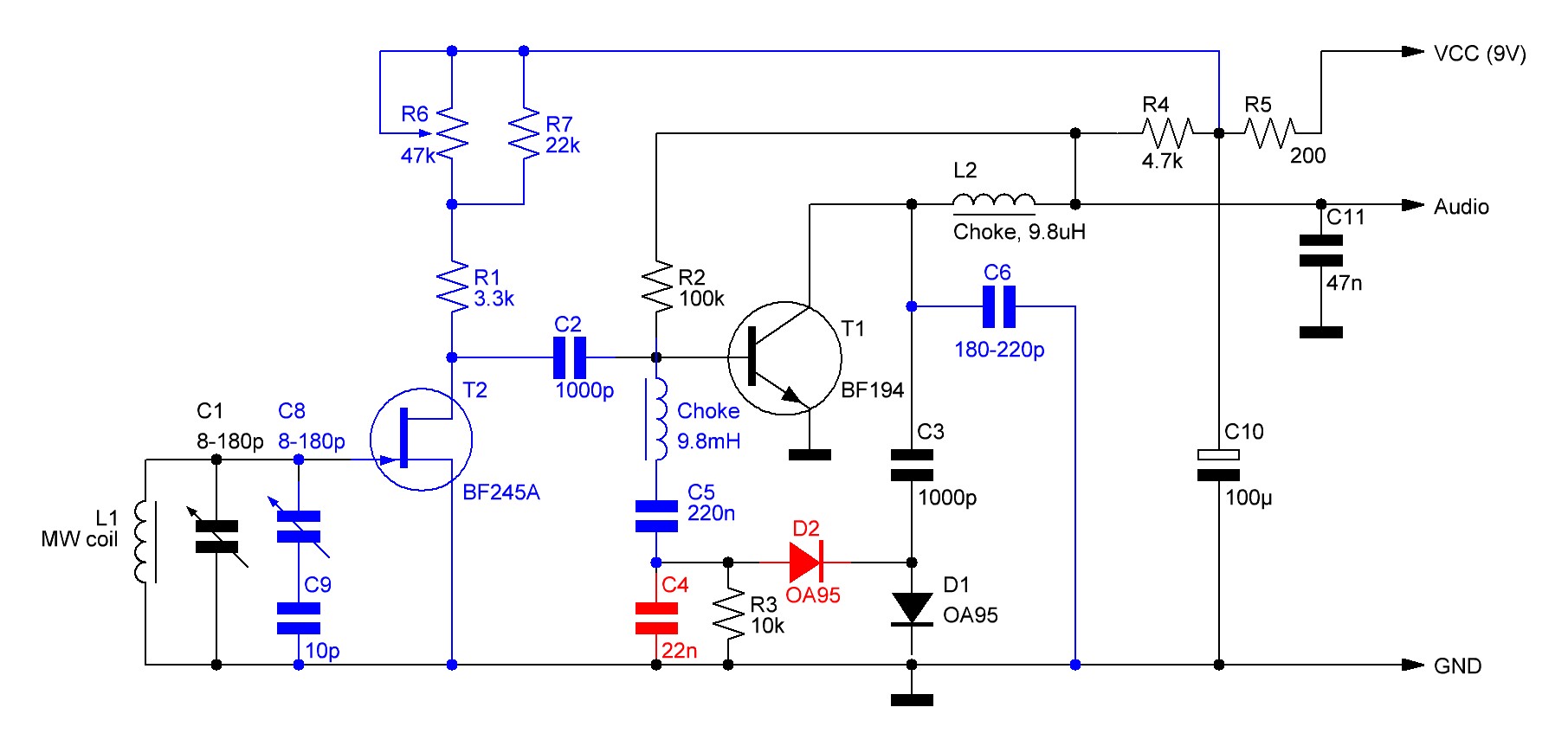
The key aspects of the circuit above are:
- Since the coil can no longer be inductively coupled to the reflex input stage, measures have to be taken to allow both the amplified HF signal from the FET-buffer as well as the AF return signal from the rectifier circuit to enter the reflex stage (BF194). The chosen solution is to add a choke coil in series with C5 to avoid the HF signal through C2 to be short-circuited (via C5 and C4) whilst allowing the AF signal from the rectifier through C5 to pass. In this sense, the combination of C2 and the added choke coil is a "mirrored" version of the C3, L2 combination in the reflex circuit.
- The buffer stage adds a very high level of amplification that has shown to lead to feedback and oscillation as a consequence. To be able to control this, R1/R6/R7 have been added to set the proper amplification levels (just below oscillation) whilst C6 counteracts oscillation effects at higher frequencies.
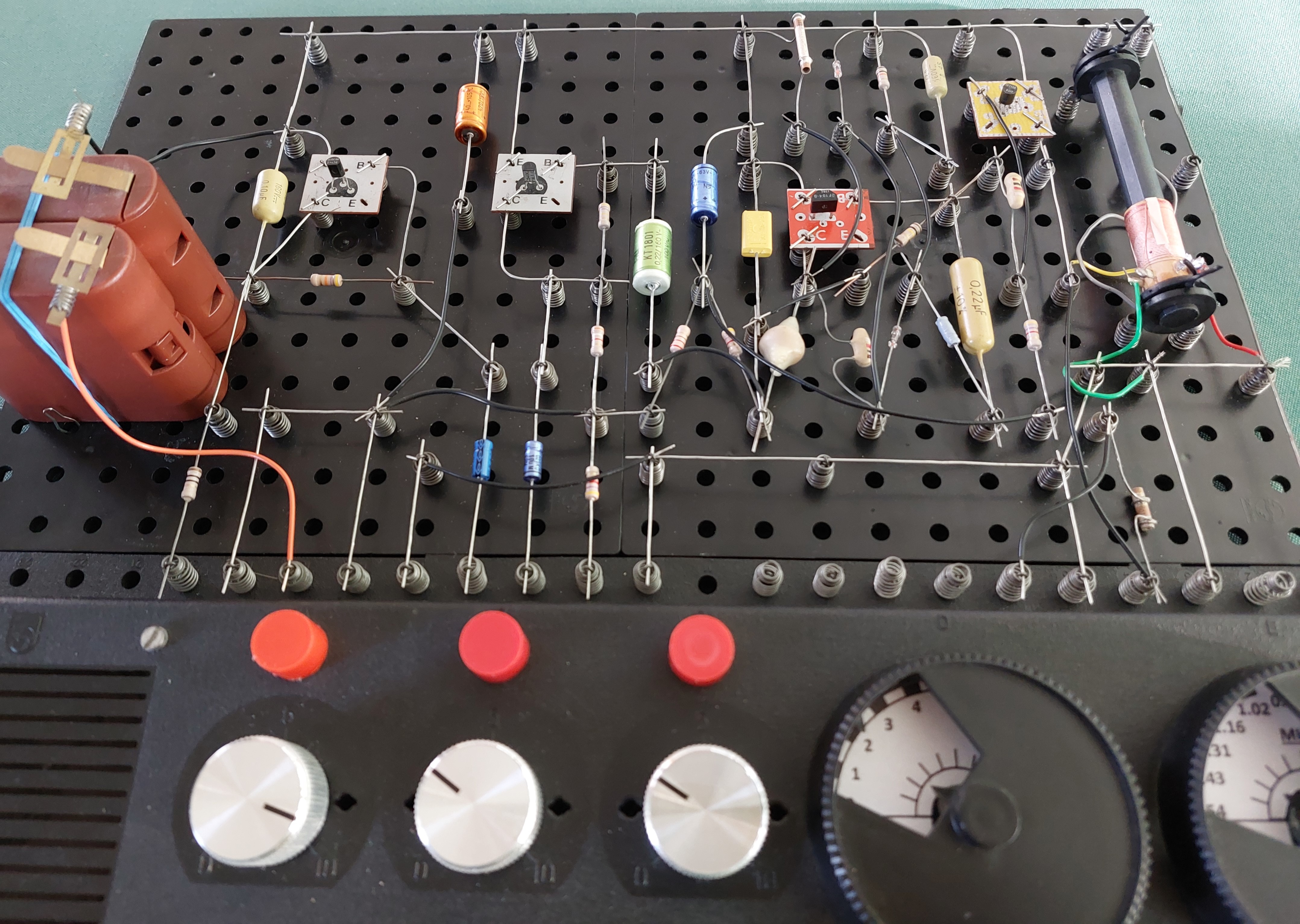
The picture below shows how the secondary MW coil (green & grey wires) is disabled: one wire is grounded, the other wire is left unconnected:
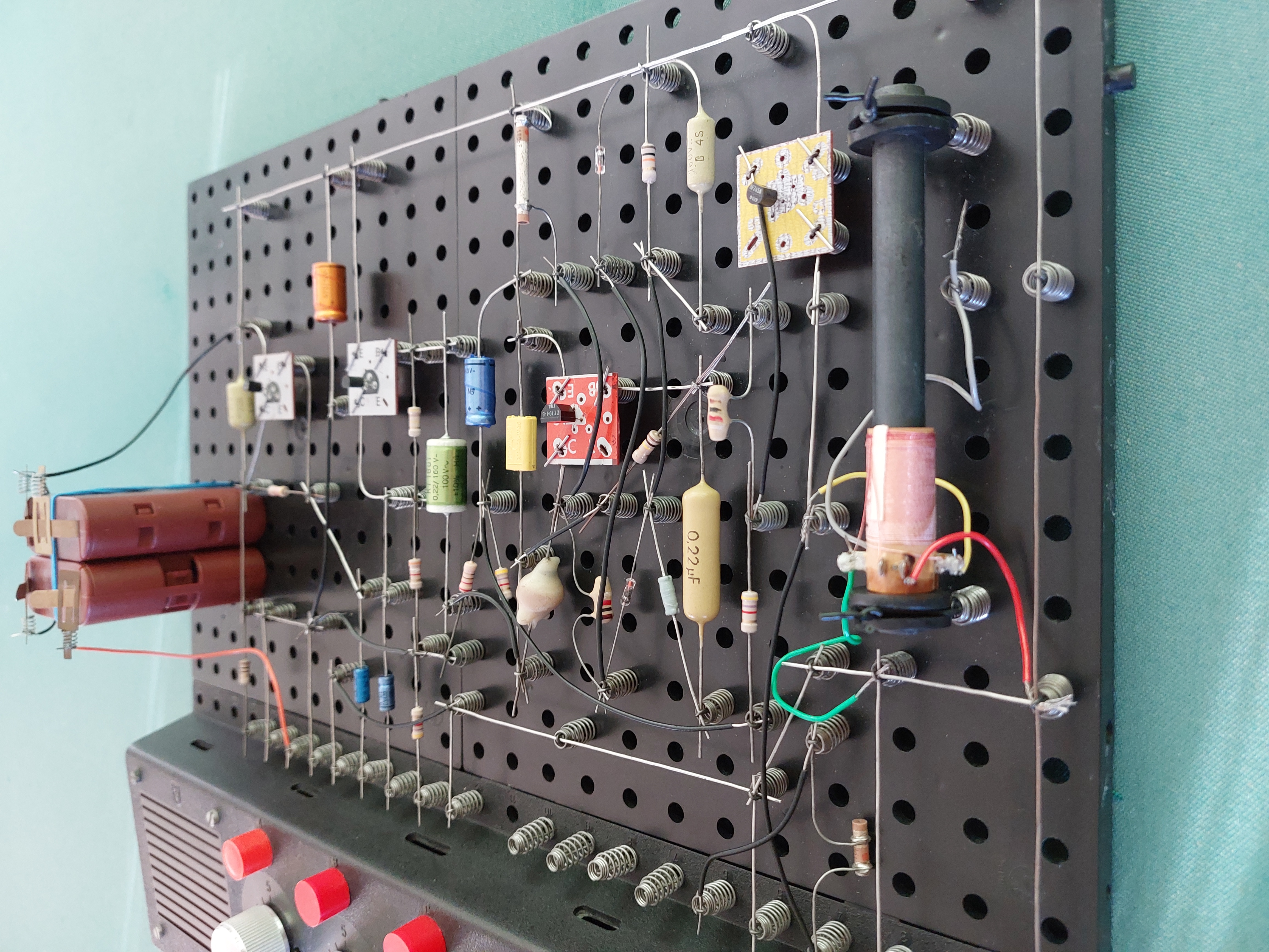
A final layout version may look like this:
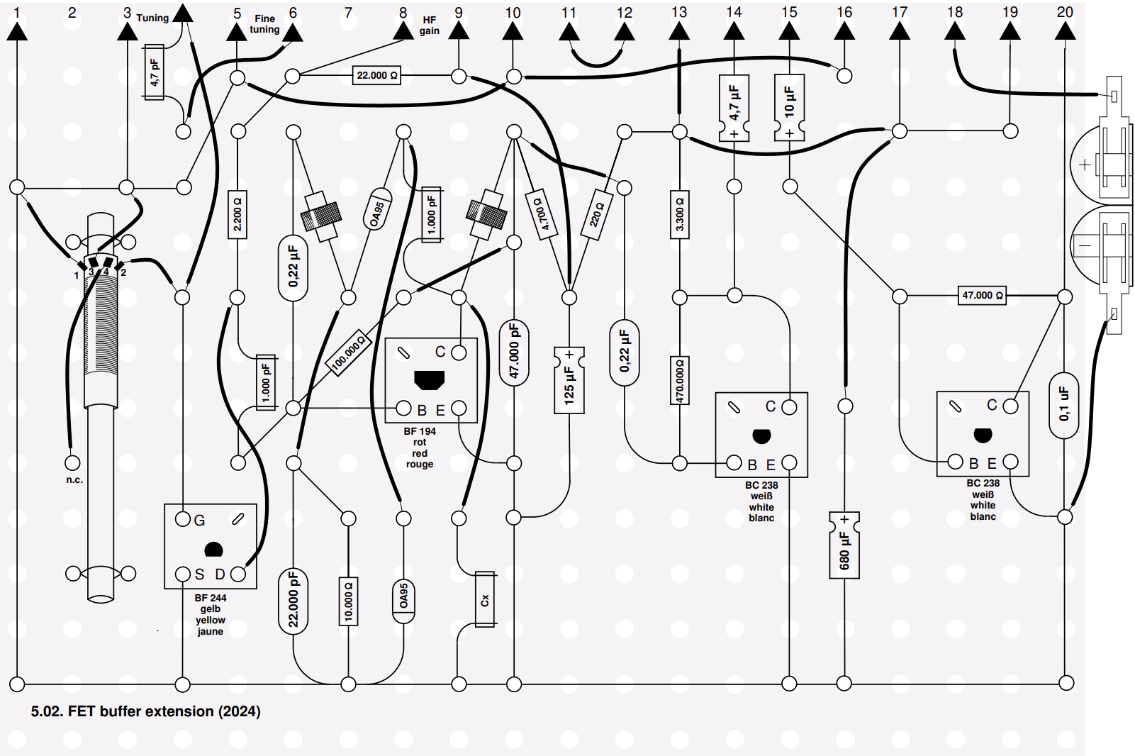
Layout design files:
- Philips EE Layout design (XFig/WinFig)
- Philips EE Layout design (PDF)